Difference between revisions of "NG 900/9-3 Cylinder Head Removal"
| Line 1: | Line 1: | ||
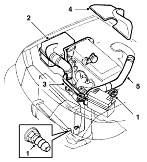
1. Drape protective covers over the wings to protect the paintwork, drain the coolant and disconnect the negative battery cable. | 1. Drape protective covers over the wings to protect the paintwork, drain the coolant and disconnect the negative battery cable. | ||
| − | [[file:Cylinder_Head_01.gif|thumbnail|none|]] | + | [[file:Cylinder_Head_01.gif|thumbnail|none|MAF; Turbo Bypass and Inlet; Delivery Pipe]] |
2. Unplug the mass air flow sensor connector and disconnect the intake hose (B206i/B234i). Remove the air cleaner. | 2. Unplug the mass air flow sensor connector and disconnect the intake hose (B206i/B234i). Remove the air cleaner. | ||
| Line 11: | Line 11: | ||
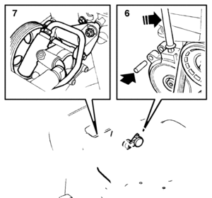
6. Relieve the belt tensioner of strain, using a ratchet handle extension, and insert a 6 mm drill in the hole as shown. Remove the belt. | 6. Relieve the belt tensioner of strain, using a ratchet handle extension, and insert a 6 mm drill in the hole as shown. Remove the belt. | ||
| − | [[file:Cylinder_Head_02.gif|thumbnail|none|]] | + | [[file:Cylinder_Head_02.gif|thumbnail|none|Release Serpentine Belt Tension]] |
| − | Important: Exercise the utmost care to ensure that the belt tensioner does not break at its end position. | + | '''Important: Exercise the utmost care to ensure that the belt tensioner does not break at its end position.''' |
7. Undo and move aside the servo pump. | 7. Undo and move aside the servo pump. | ||
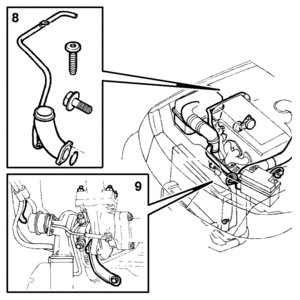
8. Remove the crankcase breather valve and inlet pipe (turbo). | 8. Remove the crankcase breather valve and inlet pipe (turbo). | ||
| − | [[file:Cylinder_Head_03.gif|thumbnail|none|]] | + | [[file:Cylinder_Head_03.gif|thumbnail|none|Crankcase Breather Valve and Inlet Pipe]] |
9. Unscrew the nuts and washers on the turbocharger or exhaust manifold. Slacken the turbocharger steady bar bolts. | 9. Unscrew the nuts and washers on the turbocharger or exhaust manifold. Slacken the turbocharger steady bar bolts. | ||
10. Disconnect the coolant hoses from the cylinder head and remove the water pipe for cooling the turbocharger from the cylinder head. | 10. Disconnect the coolant hoses from the cylinder head and remove the water pipe for cooling the turbocharger from the cylinder head. | ||
| − | |||
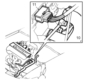
11. Unplug the ignition discharge module connector (turbo). | 11. Unplug the ignition discharge module connector (turbo). | ||
| + | [[file:Cylinder_Head_04.gif|thumbnail|none|Unplug DIC]] | ||
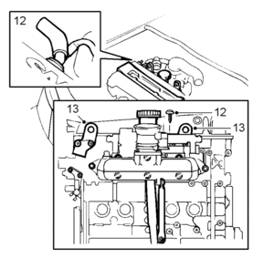
12. Remove the bracket for the dipstick tube and remove the tube. Disconnect the crankcase breather and vacuum hoses from the camshaft cover. | 12. Remove the bracket for the dipstick tube and remove the tube. Disconnect the crankcase breather and vacuum hoses from the camshaft cover. | ||
| − | [[file:Cylinder_Head_05.gif|thumbnail|none|]] | + | [[file:Cylinder_Head_05.gif|thumbnail|none|Remove Dipstick Tube]] |
13. Remove the lifting eyes at the intake manifold and move the bracket for the electrical connections to one side. | 13. Remove the lifting eyes at the intake manifold and move the bracket for the electrical connections to one side. | ||
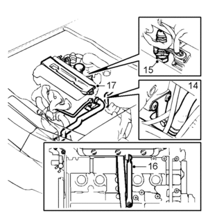
14. Disconnect the throttle body preheating hose and the bolts securing the water pipe to the thermostat housing cover. | 14. Disconnect the throttle body preheating hose and the bolts securing the water pipe to the thermostat housing cover. | ||
| − | [[file:Cylinder_Head_06.gif|thumbnail|none|]] | + | [[file:Cylinder_Head_06.gif|thumbnail|none|Throttle Body Preheat Hose]] |
15. Unplug the temperature sensor connector (adjacent to the intake manifold). | 15. Unplug the temperature sensor connector (adjacent to the intake manifold). | ||
| Line 41: | Line 41: | ||
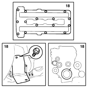
18. Remove the camshaft cover, line up the 0° mark on the flywheel with the timing mark and check that the timing marks on the camshafts are also in line. | 18. Remove the camshaft cover, line up the 0° mark on the flywheel with the timing mark and check that the timing marks on the camshafts are also in line. | ||
| − | [[file:Cylinder_Head_07.gif|thumbnail|none|]] | + | [[file:Cylinder_Head_07.gif|thumbnail|none|Camshaft Cover]] |
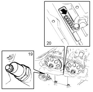
19. Remove the chain tensioner. A 27 mm socket can be used after removal of the plug with spring. | 19. Remove the chain tensioner. A 27 mm socket can be used after removal of the plug with spring. | ||
| − | [[file:Cylinder_Head_08.gif|thumbnail|none|]] | + | [[file:Cylinder_Head_08.gif|thumbnail|none|Chain Tensioner]] |
20. Remove the camshaft sprockets and position the chain so that it will not obstruct removal of the cylinder head. | 20. Remove the camshaft sprockets and position the chain so that it will not obstruct removal of the cylinder head. | ||
Latest revision as of 22:28, 9 February 2010
1. Drape protective covers over the wings to protect the paintwork, drain the coolant and disconnect the negative battery cable.
2. Unplug the mass air flow sensor connector and disconnect the intake hose (B206i/B234i). Remove the air cleaner.
3. Remove the by-pass hose and inlet hose and plug the inlet pipe (turbo).
4. Lift off the cover or the resonator.
5. Remove the delivery pipe between the charge air cooler and throttle body and plug the hose at the charge air cooler end (turbo).
6. Relieve the belt tensioner of strain, using a ratchet handle extension, and insert a 6 mm drill in the hole as shown. Remove the belt.
Important: Exercise the utmost care to ensure that the belt tensioner does not break at its end position.
7. Undo and move aside the servo pump.
8. Remove the crankcase breather valve and inlet pipe (turbo).
9. Unscrew the nuts and washers on the turbocharger or exhaust manifold. Slacken the turbocharger steady bar bolts.
10. Disconnect the coolant hoses from the cylinder head and remove the water pipe for cooling the turbocharger from the cylinder head.
11. Unplug the ignition discharge module connector (turbo).
12. Remove the bracket for the dipstick tube and remove the tube. Disconnect the crankcase breather and vacuum hoses from the camshaft cover.
13. Remove the lifting eyes at the intake manifold and move the bracket for the electrical connections to one side.
14. Disconnect the throttle body preheating hose and the bolts securing the water pipe to the thermostat housing cover.
15. Unplug the temperature sensor connector (adjacent to the intake manifold).
16. Undo the bolts securing the intake manifold steady bar, undo the nuts securing the inlet manifold to the cylinder head and move the intake manifold to one side.
17. Remove the cover plate, HT cables and distributor cap (B206i/B234i) or ignition discharge module. Remove the spark plugs.
18. Remove the camshaft cover, line up the 0° mark on the flywheel with the timing mark and check that the timing marks on the camshafts are also in line.
19. Remove the chain tensioner. A 27 mm socket can be used after removal of the plug with spring.
20. Remove the camshaft sprockets and position the chain so that it will not obstruct removal of the cylinder head.
21. Remove the cylinder head. Start with the timing cover bolts and continue in reverse assembly order.
22. Wipe up any oil that has run out. Make sure that the timing chain does not obstruct its removal and then lift off the cylinder head.
